


Introduction:
Want to enter the field of robotics? Here is a great start. This blog begins with a detailed introduction followed by assembling, coding and testing. By the end of this blog, you will be able to build your own 2-Wheel Drive Bluetooth Controlled Robot with Arduino Uno and Motor Shield. In this project we are going to see how to interface Bluetooth with Arduino to control the robot car to move in the desired path. This blog does not just aim for you to build a robot but also give a clear and detailed description in every step of the way, before we get into the details let us understand the basics.
Components
Let's start by introducing the components we will be using to make the Bluetooth controlled car, including the Arduino Uno board, Motor Driver Shield, two DC motors with the chassis, and a HC-05 Bluetooth module
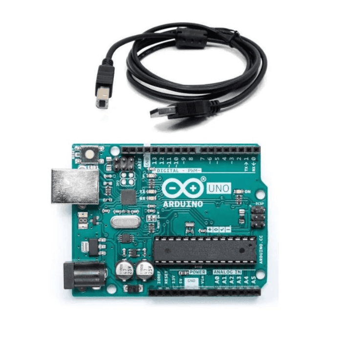
Arduino Uno

Arduino Uno is an open-source microcontroller board based on the processor ATmega328P. 6 analog pin inputs, 14 digital pins, a USB connector, a power jack, and an ICSP (In-Circuit Serial Programming) header.
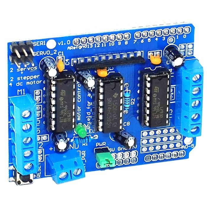
Motor Shield

Motor Shield is a driver module for motors that allows you to use Arduino to control the working speed and direction of the motor.
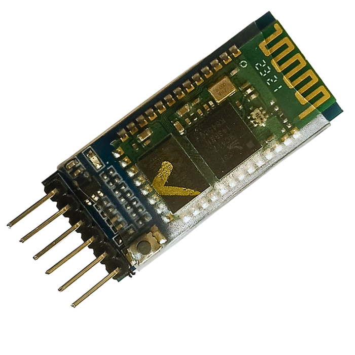
HC-05 Bluetooth module

HC-05 Bluetooth module is used as UART serial converter module which can easily transfer the UART data through the wireless Bluetooth.
Assembling:
Before the wiring we need to make a chassis that can hold Two motors and an universal wheel, well we got you covered with all the steps needed
Step 1: Assemble the Chassis and Motor
- Begin by inserting the fastener into the chassis. This fastener will serve as a secure attachment point for the motor assembly.
- Connect the wheel to the motor. Ensure that the wheel is properly aligned and firmly attached to the motor.
- Fix the motor onto the chassis, making sure it is securely mounted. The motor is a crucial component in your project, so its proper installation is vital for the device's functionality.
- Once the motor is in place, insert the screws through the designated holes and tighten them. This step ensures that the motor is firmly attached to the chassis, preventing any unnecessary movement.
- Securely fix the universal wheel on to the chassis using spacer and screws
- Firmly fix the batteries in the pre-cut holes and connect it to the driver, if there is availability of a second 9v battery, connect the other battery to the Arduino board using a male DC Jack.
Step 2: Set Up the Arduino and Motor Shield
- In this step, you will work with the electronic components of your project. Begin by inserting the motor shield onto the Arduino Uno board. The motor shield will act as an interface between the Arduino and the motors, allowing you to control their movements.
- Additionally, connect the motors and the Bluetooth module to the motor shield. This connection is essential for the communication and control of your device.
- Connecting a Jumper cable between the PWR pins is a must to ensure the power is supplies to the motors
Step 3: Connect the Motors
- Specifically, connect the left motor to the M1 pin on the motor shield. The M1 pin is designated for controlling the left motor, so make sure your connections are secure.
- Similarly, connect the right motor to the M2 pin of the motor shield. This connection ensures that the right motor is properly interfaced with the motor shield, allowing for precise control.
Step 4: Establish Bluetooth Module Connections
- In the final step, connect the Bluetooth module to the motor shield. This step is crucial for remote control and communication with your device.
- Connect the VCC (Voltage) and GND (Ground) pins of the Bluetooth module to the 5V and GND pins on the motor shield, respectively. This provides the necessary power supply for the Bluetooth module.
- Additionally, connect the TX (Transmit) and RX (Receive) pins of the Bluetooth module to the A0 and A1 pins on the motor shield. This configuration enables data exchange between the Bluetooth module and the motor shield, allowing for remote control and input.
Following these detailed steps will ensure a well-organized and functional assembly of your device, setting the foundation for further development and testing.
read our blog explaining How light dependent resistor Sensor Works, which provides comprehensive information about Light Dependent Resistors (LDRs), explaining their working principle, types, advantages, disadvantages, and applications.
Circuit Connection
|
Arduino |
Bluetooth |
|
5v |
VCC |
|
GND |
GND |
|
A0 |
TX |
|
A1 |
RX |
|
Motor Shield |
Motor |
|
M1 |
Left |
|
M2 |
Right |
Arduino Code:
Using simple Arduino programming, we can code the robot car to move it forward, backward, left, and right, as well as stopping it. The code and description of each is as follows
#include  // Library for controlling DC motors

#include


AF_DCMotorleft_motor(1); // Define motor 1 on M1

AF_DCMotorright_motor(2); // Define motor 2 on M2

SoftwareSerialBT(A0, A1); // RX, TX pins for Bluetooth (Change as needed)


void setup() {

Serial.begin(9600); // Initialize the Serial Monitor

BT.begin(9600); // Set the baud rate for the HC-05 Bluetooth module

Serial.println("Bluetooth Car Control");

}


void loop() {

if (BT.available()) {

char command = BT.read();

stop(); // Initialize with the car stopped


if (command == 'F') { // Forward

forward();

Serial.println("Forward");

} else if (command == 'B') { // Backward

backward();

Serial.println("Backward");

} else if (command == 'L') { // Left

left();

Serial.println("Left");

} else if (command == 'R') { // Right

right();

Serial.println("Right");

} else if (command == 'S') { // Stop

stop();

Serial.println("Stop");

}

}

}


void forward() {

left_motor.setSpeed(255); // Define maximum velocity

right_motor.setSpeed(255);

left_motor.run(FORWARD); // Rotate both motors forward

right_motor.run(FORWARD);

}

void backward() {

left_motor.setSpeed(255);

right_motor.setSpeed(255);

left_motor.run(BACKWARD); // Rotate both motors backward

right_motor.run(BACKWARD);

}

void left() {

left_motor.setSpeed(150);

right_motor.setSpeed(150);

left_motor.run(BACKWARD); // Rotate left motor backward

right_motor.run(FORWARD); // Rotate right motor forward

}


void right() {

left_motor.setSpeed(150);

right_motor.setSpeed(150);

left_motor.run(FORWARD); // Rotate left motor forward

right_motor.run(BACKWARD); // Rotate right motor backward

}


void stop() {

left_motor.setSpeed(0); // Motor stopped

right_motor.setSpeed(0);

left_motor.run(RELEASE); // Stop the motor

right_motor.run(RELEASE);

}
Explanation:
Library installation:
There are Two libraries that we must include, AFMotor library, which is used to control DC motors and second is the SoftwareSerial library, which is used for serial communication with a Bluetooth module.
To install a library the steps are as follows:
Arduino.IDE → Library manager → Type in the desired library → Install.
Motor Initialization:
These lines (AF_DCMotorleft_motor(1) and AF_DCMotorright_motor(2)) initialize two DC motors using the AFMotor library. The left motor is connected to motor output M1, and the right motor is connected to M2
Bluetooth Initialization:
This line (SoftwareSerial BT (A0, A1)) initializes a SoftwareSerial object named 'BT' to communicate with a Bluetooth module. It specifies the pins A0 (RX) and A1 (TX) for serial communication.
Setup Function:
The setup function is executed once when the Arduino starts. It Initializes the serial communication with the Arduino's default serial monitor at a baud rate of 9600 and also Initializes the Bluetooth module with a baud rate of 9600.
Loop Function:
The loop function continuously runs in a loop. The “BT.available()” Checks if there is any data available from the Bluetooth module. The “BT.raed()” reads a character from the Bluetooth module and stores it in the “command” variable. The code then checks the received “command” character and calls the corresponding function to control the car's movement based on the command ('F' for forward, 'B' for backward, 'L' for left, 'R' for right, 'S' for stop).
Uploading and Testing:
Now upload the code into the Arduino board and install the given application using the given link. After installing the given application, open it and connect the Bluetooth to the application and control your car using the buttons.

Conclusion:
Upon completion of this project, we can observe the robot car is following the path and directions you assign through the mobile application. This is a result of your efforts and the convergence of technology, mechanics, and creativity.
This project journey has been providing you with detailed insights into the fundamental components and their respective functions. We were able to understand about Arduino and the process to code it to provide the desired results. We also learnt to connect the different components according to the given instruction. These hands-on lessons have bridged the gap between theory and practice, allowing you to appreciate the real-world applications of these components.
Embrace your newfound expertise and curiosity, and let them guide you towards even more remarkable projects and discoveries in the future
Please do check out other blog posts about Popular electronics
Make sure you check out our wide range of products and collections (we offer some exciting deals!)