


In today's era of smart homes and interconnected devices, home automation systems have become increasingly popular. The integration of voice assistants, such as Amazon's Alexa, has further revolutionized the way we interact with our homes. In this tutorial, we will explore the fascinating world of building an ESP32 Alexa Home Automation System using an Echo Dot.
The ESP32, a powerful microcontroller with built-in Wi-Fi and Bluetooth capabilities, serves as the brain of the home automation system. By integrating it with Amazon's Echo Dot, a voice-controlled smart speaker, we can harness the power of Alexa to control and monitor various devices and functionalities within our homes.
Through this tutorial, we will guide you through the step-by-step process of setting up the ESP32 Alexa Home Automation System. We will cover the hardware components required, including the ESP32 microcontroller, Echo Dot, and other peripherals. Additionally, we will explore the necessary software configurations, including setting up the ESP32 with Arduino IDE and configuring the Alexa Skills Kit.
By the end of this tutorial, you will have a comprehensive understanding of how to create a seamless home automation system using the ESP32 and Alexa. You will be able to control lights, appliances, and other smart devices in your home with simple voice commands, enhancing comfort, convenience, and efficiency.
Whether you are a DIY enthusiast, a home automation aficionado, or someone intrigued by the possibilities of voice-controlled smart homes, this tutorial will equip you with the knowledge and skills to create your own ESP32 Alexa Home Automation System. So, let's embark on this exciting journey of bringing intelligence and voice control to your living space with the power of ESP32 and Alexa.
Purpose
The purpose of the ESP32 Alexa Home Automation System with Echo Dot is to provide a seamless and intuitive way to control and automate various aspects of our homes using voice commands. By integrating the ESP32 microcontroller with Amazon's Alexa, we can leverage the power of voice control and artificial intelligence to enhance our home automation experience.
With this system, users can effortlessly control lights, appliances, thermostats, security systems, and other smart devices by simply speaking commands to the Echo Dot. The ESP32 acts as the bridge between Alexa and the connected devices, enabling bidirectional communication and intelligent automation.
The system aims to simplify daily tasks, improve energy efficiency, enhance home security, and create a more convenient and comfortable living environment. It eliminates the need for manual operation or relying on smartphone apps, allowing users to control their smart home devices with natural voice commands from anywhere within range of the Echo Dot.
The system also promotes a hands-free and immersive user experience, enabling users to multitask, access information, and perform actions effortlessly through voice interaction. It fosters a futuristic and interconnected home environment where technology seamlessly integrates with our daily lives.
Building a prototype
Components required:
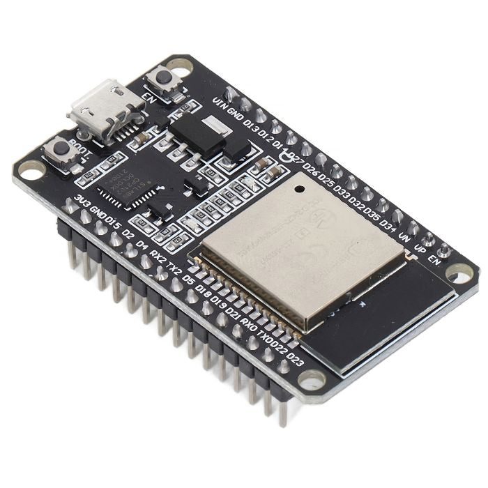
- ESP32 DEV KIT V1
- 8-channel 5V SPDT Relay Module
- Manual Switches
- Amazon Echo Dot
Circuit diagram

D23, D22, D21, D19, D18, D5, D25 & D26 GPIO are used to control the 8-channel relay module. And the GPIO D13, D12, D14, D27, D33, D32, D15 & D4 are connected with manual switches to control the relay module manually.
The INPUT_PULLUP function has been used in Arduino IDE instead of using the pull-up resistors with each switch.
According to the code, when the relay module's control pins receive a LOW signal, the corresponding relay will turn on, and when the control pin receives a HIGH signal, the relay will switch off.
You can manually operate the relays from the switches if WiFi is not available. Every 3 seconds, the ESP32 will check for WiFi. The ESP32 will automatically establish a WiFi connection once the internet is operational again.
Code:
#include

#include

#include

using namespace ace_button;


Espalexa espalexa;


#define RelayPin1 23 //D23

#define RelayPin2 22 //D22

#define RelayPin3 21 //D21

#define RelayPin4 19 //D19

#define RelayPin5 18 //D18

#define RelayPin6 5 //D5

#define RelayPin7 25 //D25

#define RelayPin8 26 //D26


#define SwitchPin1 13 //D13

#define SwitchPin2 12 //D12

#define SwitchPin3 14 //D14

#define SwitchPin4 27 //D27

#define SwitchPin5 33 //D33

#define SwitchPin6 32 //D32

#define SwitchPin7 15 //D15

#define SwitchPin8 4 //D4


#define wifiLed 2 //D2


// WiFi Credentials

const char* ssid = "WiFi Name";

const char* password = "WiFi Password";


// device names

String Device_1_Name = "Study Lamp";

String Device_2_Name = "CFL";

String Device_3_Name = "Yellow light";

String Device_4_Name = "Night Lamp";

String Device_5_Name = "Studio Light";

String Device_6_Name = "Outdoor Light";

String Device_7_Name = "Kitchen Light";

String Device_8_Name = "Room Light";


// prototypes

boolean connectWifi();


//callback functions

void firstLightChanged(uint8_t brightness);

void secondLightChanged(uint8_t brightness);

void thirdLightChanged(uint8_t brightness);

void fourthLightChanged(uint8_t brightness);

void fifthLightChanged(uint8_t brightness);

void sixthLightChanged(uint8_t brightness);

void senventhLightChanged(uint8_t brightness);

void eighthLightChanged(uint8_t brightness);


ButtonConfig config1;

AceButton button1(&config1);

ButtonConfig config2;

AceButton button2(&config2);

ButtonConfig config3;

AceButton button3(&config3);

ButtonConfig config4;

AceButton button4(&config4);

ButtonConfig config5;

AceButton button5(&config5);

ButtonConfig config6;

AceButton button6(&config6);

ButtonConfig config7;

AceButton button7(&config7);

ButtonConfig config8;

AceButton button8(&config8);


void handleEvent1(AceButton*, uint8_t, uint8_t);

void handleEvent2(AceButton*, uint8_t, uint8_t);

void handleEvent3(AceButton*, uint8_t, uint8_t);

void handleEvent4(AceButton*, uint8_t, uint8_t);

void handleEvent5(AceButton*, uint8_t, uint8_t);

void handleEvent6(AceButton*, uint8_t, uint8_t);

void handleEvent7(AceButton*, uint8_t, uint8_t);

void handleEvent8(AceButton*, uint8_t, uint8_t);


boolean wifiConnected = false;


void firstLightChanged(uint8_t brightness)

{


if (brightness == 255)

{

digitalWrite(RelayPin1, LOW);

Serial.println("Device1 ON");

}

else

{

digitalWrite(RelayPin1, HIGH);

Serial.println("Device1 OFF");

}

}


void secondLightChanged(uint8_t brightness)

{

//Control the device

if (brightness == 255)

{

digitalWrite(RelayPin2, LOW);

Serial.println("Device2 is ON");

}

else

{

digitalWrite(RelayPin2, HIGH);

Serial.println("Device2 is OFF");

}

}


void thirdLightChanged(uint8_t brightness)

{

//Control the device

if (brightness == 255)

{

digitalWrite(RelayPin3, LOW);

Serial.println("Device3 ON");

}

else

{

digitalWrite(RelayPin3, HIGH);

Serial.println("Device3 OFF");

}

}


void fourthLightChanged(uint8_t brightness)

{

//Control the device

if (brightness == 255)

{

digitalWrite(RelayPin4, LOW);

Serial.println("Device4 ON");

}

else

{

digitalWrite(RelayPin4, HIGH);

Serial.println("Device4 OFF");

}

}


void fifthLightChanged(uint8_t brightness)

{

//Control the device

if (brightness == 255)

{

digitalWrite(RelayPin5, LOW);

Serial.println("Device5 ON");

}

else

{

digitalWrite(RelayPin5, HIGH);

Serial.println("Device1 OFF");

}

}


void sixthLightChanged(uint8_t brightness)

{

//Control the device

if (brightness == 255)

{

digitalWrite(RelayPin6, LOW);

Serial.println("Device6 ON");

}

else

{

digitalWrite(RelayPin6, HIGH);

Serial.println("Device6 OFF");

}

}


void seventhLightChanged(uint8_t brightness)

{

//Control the device

if (brightness == 255)

{

digitalWrite(RelayPin7, LOW);

Serial.println("Device7 ON");

}

else

{

digitalWrite(RelayPin7, HIGH);

Serial.println("Device7 OFF");

}

}


void eighthLightChanged(uint8_t brightness)

{


if (brightness == 255)

{

digitalWrite(RelayPin8, LOW);

Serial.println("Device8 ON");

}

else

{

digitalWrite(RelayPin8, HIGH);

Serial.println("Device8 OFF");

}

}


boolean connectWifi()

{

boolean state = true;

int i = 0;


WiFi.mode(WIFI_STA);

WiFi.begin(ssid, password);

Serial.println("");

Serial.println("Connecting to WiFi");


// Wait for connection

Serial.print("Connecting...");

while (WiFi.status() != WL_CONNECTED) {

delay(500);

Serial.print(".");

if (i > 20) {

state = false; break;

}

i++;

}

Serial.println("");

if (state) {

Serial.print("Connected to ");

Serial.println(ssid);

Serial.print("IP address: ");

Serial.println(WiFi.localIP());

}

else {

Serial.println("Connection failed.");

}

return state;

}


void addDevices(){

// Define your devices here.

espalexa.addDevice(Device_1_Name, firstLightChanged); //simplest definition, default state off

espalexa.addDevice(Device_2_Name, secondLightChanged);

espalexa.addDevice(Device_3_Name, thirdLightChanged);

espalexa.addDevice(Device_4_Name, fourthLightChanged);

espalexa.addDevice(Device_5_Name, fifthLightChanged);

espalexa.addDevice(Device_6_Name, sixthLightChanged);

espalexa.addDevice(Device_7_Name, seventhLightChanged);

espalexa.addDevice(Device_8_Name, eighthLightChanged);


espalexa.begin();

}


void setup()

{

Serial.begin(115200);


pinMode(RelayPin1, OUTPUT);

pinMode(RelayPin2, OUTPUT);

pinMode(RelayPin3, OUTPUT);

pinMode(RelayPin4, OUTPUT);

pinMode(RelayPin5, OUTPUT);

pinMode(RelayPin6, OUTPUT);

pinMode(RelayPin7, OUTPUT);

pinMode(RelayPin8, OUTPUT);


pinMode(wifiLed, OUTPUT);


pinMode(SwitchPin1, INPUT_PULLUP);

pinMode(SwitchPin2, INPUT_PULLUP);

pinMode(SwitchPin3, INPUT_PULLUP);

pinMode(SwitchPin4, INPUT_PULLUP);

pinMode(SwitchPin5, INPUT_PULLUP);

pinMode(SwitchPin6, INPUT_PULLUP);

pinMode(SwitchPin7, INPUT_PULLUP);

pinMode(SwitchPin8, INPUT_PULLUP);


//During Starting all Relays should TURN OFF

digitalWrite(RelayPin1, HIGH);

digitalWrite(RelayPin2, HIGH);

digitalWrite(RelayPin3, HIGH);

digitalWrite(RelayPin4, HIGH);

digitalWrite(RelayPin5, HIGH);

digitalWrite(RelayPin6, HIGH);

digitalWrite(RelayPin7, HIGH);

digitalWrite(RelayPin8, HIGH);


config1.setEventHandler(button1Handler);

config2.setEventHandler(button2Handler);

config3.setEventHandler(button3Handler);

config4.setEventHandler(button4Handler);

config5.setEventHandler(button5Handler);

config6.setEventHandler(button6Handler);

config7.setEventHandler(button7Handler);

config8.setEventHandler(button8Handler);


button1.init(SwitchPin1);

button2.init(SwitchPin2);

button3.init(SwitchPin3);

button4.init(SwitchPin4);

button5.init(SwitchPin5);

button6.init(SwitchPin6);

button7.init(SwitchPin7);

button8.init(SwitchPin8);


// Initialise wifi connection

wifiConnected = connectWifi();


if (wifiConnected)

{

addDevices();

}

else

{

Serial.println("Cannot connect to WiFi. So in Manual Mode");

delay(1000);

}

}


void loop()

{

if (WiFi.status() != WL_CONNECTED)

{

//Serial.print("WiFi Not Connected ");

digitalWrite(wifiLed, LOW); //Turn off WiFi LED

}

else

{


digitalWrite(wifiLed, HIGH);

if (wifiConnected){

espalexa.loop();

delay(1);

}

else {

wifiConnected = connectWifi(); // Initialise wifi connection

if(wifiConnected){

addDevices();

}

}

}

button1.check();

button2.check();

button3.check();

button4.check();

button5.check();

button6.check();

button7.check();

button8.check();

}


void button1Handler(AceButton* button, uint8_t eventType, uint8_t buttonState) {

Serial.println("EVENT1");

EspalexaDevice* d1 = espalexa.getDevice(0); //this will get "first device", the index is zero-based

switch (eventType) {

case AceButton::kEventPressed:

Serial.println("kEventPressed");

d1->setPercent(100); //set value "brightness" in percent

digitalWrite(RelayPin1, LOW);

break;

case AceButton::kEventReleased:

Serial.println("kEventReleased");

d1->setPercent(0); //set value "brightness" in percent

digitalWrite(RelayPin1, HIGH);

break;

}

}


void button2Handler(AceButton* button, uint8_t eventType, uint8_t buttonState) {

Serial.println("EVENT2");

EspalexaDevice* d2 = espalexa.getDevice(1);

switch (eventType) {

case AceButton::kEventPressed:

Serial.println("kEventPressed");

d2->setPercent(100);

digitalWrite(RelayPin2, LOW);

break;

case AceButton::kEventReleased:

Serial.println("kEventReleased");

d2->setPercent(0);

digitalWrite(RelayPin2, HIGH);

break;

}

}


void button3Handler(AceButton* button, uint8_t eventType, uint8_t buttonState) {

Serial.println("EVENT3");

EspalexaDevice* d3 = espalexa.getDevice(2);

switch (eventType) {

case AceButton::kEventPressed:

Serial.println("kEventPressed");

d3->setPercent(100);

digitalWrite(RelayPin3, LOW);

break;

case AceButton::kEventReleased:

Serial.println("kEventReleased");

d3->setPercent(0);

digitalWrite(RelayPin3, HIGH);

break;

}

}


void button4Handler(AceButton* button, uint8_t eventType, uint8_t buttonState) {

Serial.println("EVENT4");

EspalexaDevice* d4 = espalexa.getDevice(3);

switch (eventType) {

case AceButton::kEventPressed:

Serial.println("kEventPressed");

d4->setPercent(100);

digitalWrite(RelayPin4, LOW);

break;

case AceButton::kEventReleased:

Serial.println("kEventReleased");

d4->setPercent(0);

digitalWrite(RelayPin4, HIGH);

break;

}

}


void button5Handler(AceButton* button, uint8_t eventType, uint8_t buttonState) {

Serial.println("EVENT5");

EspalexaDevice* d5 = espalexa.getDevice(4);

switch (eventType) {

case AceButton::kEventPressed:

Serial.println("kEventPressed");

d5->setPercent(100);

digitalWrite(RelayPin5, LOW);

break;

case AceButton::kEventReleased:

Serial.println("kEventReleased");

d5->setPercent(0);

digitalWrite(RelayPin5, HIGH);

break;

}

}


void button6Handler(AceButton* button, uint8_t eventType, uint8_t buttonState) {

Serial.println("EVENT6");

EspalexaDevice* d6 = espalexa.getDevice(5);

switch (eventType) {

case AceButton::kEventPressed:

Serial.println("kEventPressed");

d6->setPercent(100);

digitalWrite(RelayPin6, LOW);

break;

case AceButton::kEventReleased:

Serial.println("kEventReleased");

d6->setPercent(0);

digitalWrite(RelayPin6, HIGH);

break;

}

}


void button7Handler(AceButton* button, uint8_t eventType, uint8_t buttonState) {

Serial.println("EVENT7");

EspalexaDevice* d7 = espalexa.getDevice(6);

switch (eventType) {

case AceButton::kEventPressed:

Serial.println("kEventPressed");

d7->setPercent(100);

digitalWrite(RelayPin7, LOW);

break;

case AceButton::kEventReleased:

Serial.println("kEventReleased");

d7->setPercent(0);

digitalWrite(RelayPin7, HIGH);

break;

}

}


void button8Handler(AceButton* button, uint8_t eventType, uint8_t buttonState) {

Serial.println("EVENT8");

EspalexaDevice* d8 = espalexa.getDevice(7);

switch (eventType) {

case AceButton::kEventPressed:

Serial.println("kEventPressed");

d8->setPercent(100);

digitalWrite(RelayPin8, LOW);

break;

case AceButton::kEventReleased:

Serial.println("kEventReleased");

d8->setPercent(0);

digitalWrite(RelayPin8, HIGH);

break;

}

}
In the code, type the following WiFi password:
- The WiFi Name at "WiFi Name"
- Password for WiFi at "WiFi Password"
Put the device names in the code after that. The name mentioned in the code will be used by Alexa to recognise that device.
Select the board as DOIT ESP32 DEVKIT V1 and the PORT in Arduino IDE. Then click on the upload button to program the ESP32 board.
After the code is uploaded, if the ESP32 connects with internet, the blue LED should turn on.

The ESP32, Amazon Echo Dot, and smartphone should be connected to the same Wifi network while configuring the Amazon Alexa App.
Working of the project
The ESP32 Alexa Home Automation System with Echo Dot requires several components to function effectively. Let's delve into the details of each component and how they work together:
- ESP32 DEV KIT V1: The ESP32 microcontroller serves as the central control unit of the system. It features built-in Wi-Fi and Bluetooth capabilities, enabling communication with other devices and connectivity to the internet.
- 8-channel 5V SPDT Relay Module: The relay module acts as a switch to control various electrical devices. It allows the low-voltage signals from the ESP32 to control the higher-voltage devices, ensuring safe and reliable switching.
- Manual Switches: Manual switches provide an alternative control method alongside voice commands. These switches enable users to manually turn devices on or off without relying solely on voice control.
- Amazon Echo Dot: The Echo Dot acts as the voice interface for the system. It connects to the ESP32 via Wi-Fi and communicates voice commands to trigger actions or control devices.
The working of the project involves a series of steps:
- Hardware Setup: Connect the ESP32, relay module, manual switches, and power supply as per the circuit diagram. Ensure the proper wiring and connections are made to facilitate communication and power transfer.
- Software Configuration: Program the ESP32 using Arduino IDE or other suitable development environments. Configure the ESP32 to connect to the Wi-Fi network and establish communication with the Amazon Alexa cloud.
- Alexa Skill Setup: Set up the necessary Alexa Skills using the Alexa Developer Console. Define the voice commands and their corresponding actions for controlling the devices connected to the ESP32.
- Voice Control: Use the Echo Dot to issue voice commands to control the connected devices. When a voice command is received, the Echo Dot sends the request to the Alexa cloud, which then communicates with the ESP32.
- ESP32 Processing: The ESP32 receives the voice command from the Alexa cloud and processes it accordingly. It determines the action associated with the command and controls the relay module to switch the devices on or off.
- Manual Control: The system also allows for manual control using the physical switches connected to the relay module. Users can override voice control by manually toggling the switches to activate or deactivate the devices.
By following these steps, the ESP32 Alexa Home Automation System enables seamless control of devices using both voice commands and manual switches. It provides a flexible and convenient approach to home automation, empowering users to control their environment based on their preferences and needs.
Conclusion
The amalgamation of the ESP32 microcontroller, 8-channel 5V SPDT relay module, manual switches, and the Amazon Echo Dot in the realm of the Alexa Home Automation System represents a remarkable feat of technological integration and intelligent control. This sophisticated ensemble brings forth a symphony of interconnected components that harmoniously respond to voice commands and manual inputs, transforming our living spaces into intelligent domains of convenience and efficiency.
Through the ESP32 microcontroller's advanced capabilities and the relay module's adept switching prowess, the system bridges the gap between traditional devices and the realm of voice-controlled automation. With the omnipresent Echo Dot as the conductor, users are empowered to orchestrate their environment with natural and effortless voice commands, transcending the boundaries of conventional control mechanisms.
The utilization of manual switches alongside the voice control functionality adds an extra layer of flexibility and user interaction, affording individuals the freedom to adapt to their preferred mode of control. This fusion of tactile and auditory command interfaces elevates the system to a realm of adaptability and intuitive usability.
If you appreciate our work don't forget to share this post and leave your opinion in the comment box.
Please do check out other blog posts about Popular electronics
Make sure you check out our wide range of products and collections (we offer some exciting deals!)