


Introduction:
In the world of electronics tinkering and creative projects, few things capture the imagination like the combination of LCD displays and Arduino microcontrollers. LCDs, or liquid crystal displays, are the artist's canvas of the electronics industry. They serve as the unique conduits that transform data into attractive images. bridging the gap between analogue and digital information. Together with the creativity of the Arduino board, these adaptable displays open up an explosion of colourful ideas. Get ready to take a tour through the fundamentals of LCD displays and their smooth integration with Arduino, and look at fascinating projects that will motivate your inner creator. When combined with the adaptable Arduino platform, these displays transform into dynamic canvases that enable you to exhibit data, communicate with users, and bring your ideas to reality.
An LCD display is a compact digital screen that can show simple words and symbols. Think of it as a tiny signboard with two rows, each fitting about 16 letters or numbers. With Arduino's compatibility and programming capabilities, we can easily interface with LCD displays to create interactive and visually appealing projects. LCD displays offer a wide range of applications, from simple digital clocks and temperature displays to more complex projects like menu systems and gaming consoles. The ability to control the amount of light passing through the liquid crystals allows for high contrast and sharp images on the display. Whether you are a student or a hobbyist, Arduino's compatibility to interface with LCD displays opens up multiple opportunities for innovative and interactive projects.
This guide is your pathway to unlocking the potential of LCD displays when teamed up with Arduino. We will take you on an exciting journey through this blog, tell you about the pin configuration of an LCD display, show you how to integrate an LCD display with an Arduino UNO, and go through some interactive projects like Digital Thermometer and clock.
read more : Top 10 Arduino Projects to Get Started With

Understanding LCD Displays:
LCD screens come in a wide variety of shapes and sizes, including the complicated 16x2 and 16x4 variations that we're now investigating. Within the realm of both 16x2 and 16x4 displays, their number labels simply capture the core of their unique characteristics. Imagine a screen that is separated into neat rows and columns, similar to a large window with delicately framed panes. These displays may be connected in either 4 bit or 8-bit mode. Since 4-bit wiring requires four fewer wires than 8-bit wiring, 4-bit wiring is typically recommended for LCD wiring. For the purposes of this tutorial, we will connect the LCD in 4-bit mode.
The 16x2 layout demonstrates its strength by enabling the display of an arrangement of 16 characters spread over two rows, creating a canvas that is both concise and versatile. The 16x2 LCD refers to a liquid crystal display that can display 16 characters in a layout spread over two rows. It is commonly used in various applications due to its compact yet versatile design. Similarly, the 16x4 LCD can display 16 characters in a layout spread over four rows, providing even more flexibility in displaying information. Both the 16x2 and 16x4 LCDs can be connected using either 4 bit or 8-bit mode, with the former being recommended for its simpler wiring requirements.
read more : Obstacle Avoidance Robot with Ultrasonic Sensors using Arduino

Pinout:
In order to better understand each pin's function and role on a typical 16x2 character LCD display, let's look at the following:
Positive Supply (+5V or VCC):
The positive supply pin is where the display gets its power. It connects to the positive side of the power supply, often around +5 volts. This voltage powers the internal circuits and segments of the LCD.
Ground (GND):
This pin is connected to the negative power supply to complete the electrical circuit. By providing a reference point for the display's voltage, it ensures that everything operates smoothly.
Contrast Control (V0):
The contrast control pin is a bit like a dimmer switch for the characters on the screen. By applying a voltage to this pin, you can make the characters darker or lighter, increasing visibility based on your preference.
Register Select (RS):
RS is like a communication filter. When it's set to 0, the data you're sending is treated as a command, telling the LCD what to do (like "go to the next line"). When set to 1, the data is seen as text to display. It's like distinguishing between giving orders and sharing information.
Read/Write (RW):
This pin indicates whether you're reading from or writing to the display. In most applications, it's set to writing mode (0) because reading from the display isn't as common. When set to writing mode, you can send commands or text data to the LCD. However, if you set it to reading mode (1), you can retrieve data from the display, such as the current position of the cursor or the status of the display.
Enable (E):
The pin E (enable) represents the sending button. The display will be alerted when you pulse this pin: "Hey, I'm sending you something!" It is a signal that instructs the display to process any incoming data that is present on the data pins.
Data Pins (D0-D7):
These pins are the communication lanes. They carry the actual data, such as letters, numbers, or even graphical patterns. The data pins are responsible for carrying the bits of information that make up the content displayed on the screen. These data pins work in conjunction with the enable pin to ensure that the incoming data is processed correctly and accurately displayed on the screen.
Backlight Control (A and K):
If your display has a backlight, these pins manage its lighting. The "A" pin connects to the positive side of the backlight, while the "K" pin connects to the negative side. This setup lets you control when the backlight shines, increasing visibility in darker environments.
read more : Arduino Hacks we bet you did not know!
Integrating the LCD Displays with Arduino UNO:
The interfacing of an LCD display with the Arduino UNO is a straightforward process that allows you to display text and graphics on the screen. The Arduino UNO has a limited number of digital pins, so it's important to use them efficiently when connecting an LCD display. One common type of LCD display used with the Arduino UNO is the 16x2 LCD module, which has 16 columns and 2 rows of characters. To integrate the Arduino UNO with an LCD display, first make sure that each pin is connected on the breadboard correctly, and then place the LCD screen and potentiometer on that breadboard.

To power the LCD and backlight, attach the positive (5V) and negative (GND) Arduino pins to the respective power rails on the breadboard. Connect the LCD's pins 2 and 15 to the positive power supply and pins 1 and 16 to the negative power supply, respectively. Connect LCD Pin 3 to the centre pin of the potentiometer to adjust the contrast, then connect the remaining pins of the potentiometer to the GND and 5V terminals. For register selection, connect LCD Pin 4 to Arduino Pin 12, LCD Pin 5 to GND, and LCD Pin 6 to Arduino Pin 10 for data enabling. Use the four-bit LCD's data pins 4, 5, 6, and 7 to connect to Arduino pins 5, 4, 3, and 2, respectively. Once all the connections are made, upload the code to the Arduino, and you should see the LCD display come to life with adjustable contrast.
read more : Arduino Uno Pin Diagram: A Complete Guide
LCD Arduino Code:
After doing the connection of Arduino UNO and LCD display, let’s go to learn the programming with LCD display. Here are some example codes for printing “Hello world!”, displaying custom Character and
Printing “Hello world”:
#include

const int rs = 12, en = 11, d4 = 5, d5 = 4, d6 = 3, d7 = 2;

LiquidCrystal lcd(rs, en, d4, d5, d6, d7);


void setup() {

// set up the LCD's number of columns and rows:

lcd.begin(16, 2);

// Print a message to the LCD.

lcd.print("Hello, world!");

}


void loop() {

lcd.setCursor(0, 1);

// print the number of seconds since reset:

lcd.print(millis() / 1000);

}
Displaying Custom Character:
#include

LiquidCrystal lcd(12, 11, 5, 4, 3, 2);


// make some custom characters:

byte heart[8] = {

0b00000,

0b01010,

0b11111,

0b11111,

0b11111,

0b01110,

0b00100,

0b00000

};


byte smiley[8] = {

0b00000,

0b00000,

0b01010,

0b00000,

0b00000,

0b10001,

0b01110,

0b00000

};


byte frownie[8] = {

0b00000,

0b00000,

0b01010,

0b00000,

0b00000,

0b00000,

0b01110,

0b10001

};


byte armsDown[8] = {

0b00100,

0b01010,

0b00100,

0b00100,

0b01110,

0b10101,

0b00100,

0b01010

};


byte armsUp[8] = {

0b00100,

0b01010,

0b00100,

0b10101,

0b01110,

0b00100,

0b00100,

0b01010

};


void setup() {

lcd.begin(16, 2);

lcd.createChar(0, heart);

lcd.createChar(1, smiley);

lcd.createChar(2, frownie);

lcd.createChar(3, armsDown);

lcd.createChar(4, armsUp);

lcd.setCursor(0, 0);

lcd.print("I ");

lcd.write(byte(0));

lcd.print(" Arduino! ");

lcd.write((byte)1);

}


void loop() {

lcd.setCursor(4, 1);

lcd.write(3);

delay(2000);

lcd.setCursor(4, 1);

lcd.write(4);

delay(2000);

}
Crafting with LCD Displays:
As we navigate through the pin description, we see the connection between the Arduino and LCD display and see text and characters on the LCD display. Now, it's time to unlock the power of these displays with some projects combining technology and creativity. One exciting project idea is to create a digital thermometer using an Arduino, an LM35 temperature sensor, and an LCD display. By uploading the code onto the Arduino, we can display the temperature on the LCD screen. Another project could be designing a simple calculator using the LCD screen and keypad. After interfacing the keypad and LCD display with the Arduino, we can make a calculator that can perform simple calculations.
read more : Top 10 Robotic Projects for Beginners
Digital thermometer:
In this project, we integrate the LM35 temperature sensor with Arduino to make a digital thermometer that measures the temperature and displays the measured temperature directly on the LCD display. Connect the LCD display to the Arduino UNO, and then connect the LM35 sensor pin to the Arduino UNO as mentioned in the diagram below. After uploading the code onto the Arduino board, the measured temperature was shown on the LCD display.

Component Required:
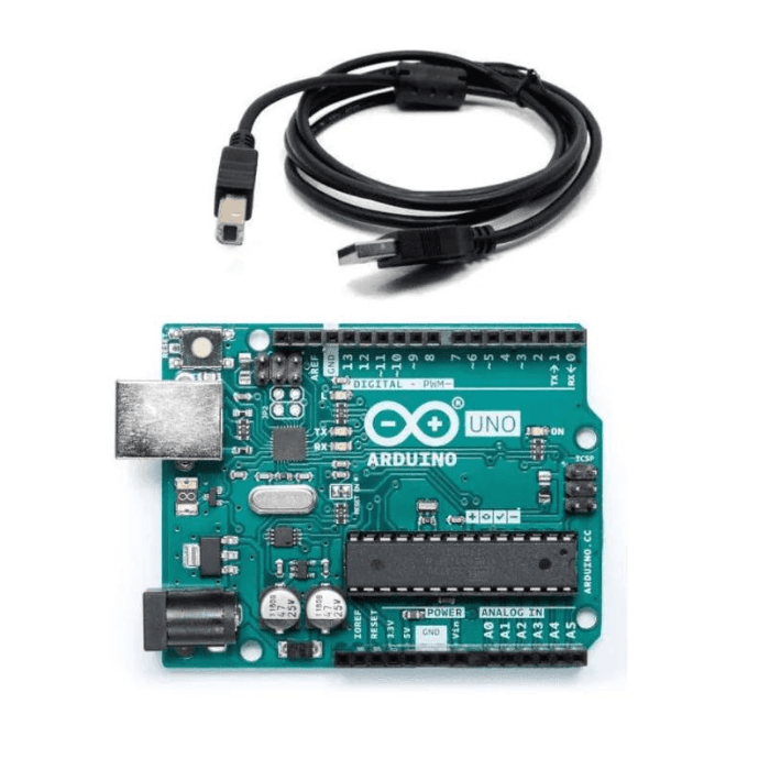
- Arduino UNO board
- LCD display
- LM35 temperature sensor
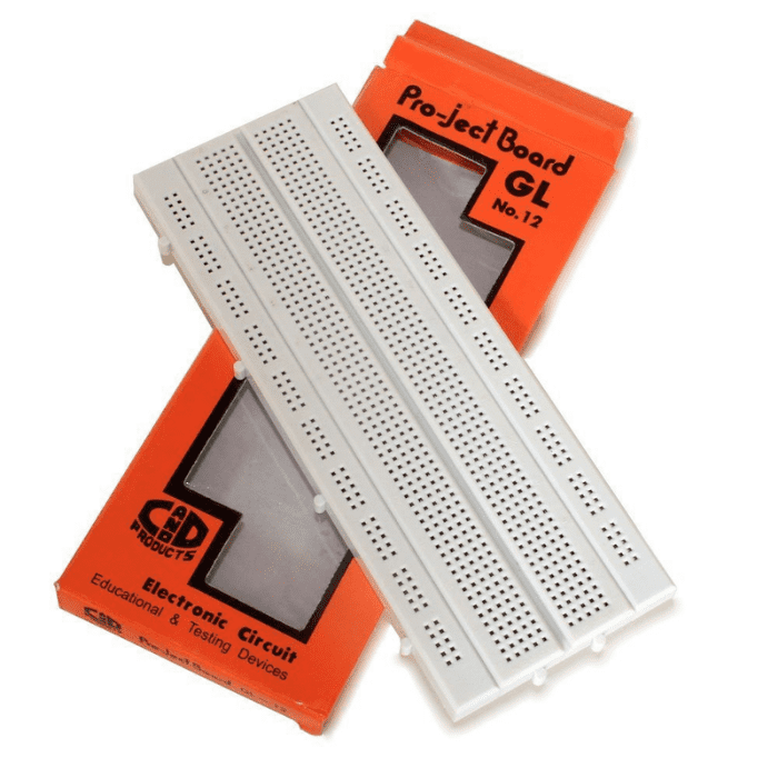
- Breadboard
- Potentiometer
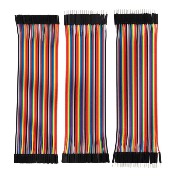
- Jumper wires
read more : Water Level Indicator: Interfacing water level sensor With Arduino
Program:
#include

LiquidCrystal lcd(12, 11, 5, 4, 3, 2);

#define LM35_sensor A0

byte degree[8]={

0b00011,

0b00011,

0b00000,

0b00000,

0b00000,

0b00000,

0b00000,

0b00000

};


void setup() {

lcd.begin(16,2);

lcd.createChar(1, degree);

lcd.setCursor(0,0);

lcd.print(" DIGITAL ");

lcd.setCursor(0,1);

lcd.print(" THERMOMETER ");

delay(2000);

lcd.clear();


}


void loop() {

float analog_read = analogRead(LM35_sensor);

float temp = analog_read/2.046 ;

delay(10);

lcd.clear();

lcd.setCursor(2,0);

lcd.print("TEMPERATURE");

lcd.setCursor(4,1);

lcd.print(temp);

lcd.write(1);// READ ASCII VALUE

lcd.print("C");

delay(1000);

}
Simple calculator:
In this project, we will build our own calculator with Arduino and LCD display. The calculator will have basic mathematical operations such as addition, subtraction, multiplication, and division. The Arduino will be configured to accept input from the keypad and show the outcome on the LCD screen. This project will provide us with practical experience with electronics and programming and help us understand how a calculator works.

Connect the LCD display and keypad with the Arduino Uno according to the given diagram and upload the code. After uploading the code to the Arduino UNO, you can do a simple calculation using it.
Component Required:
read more : What is Arduino Nano
Program:
#include

#include

LiquidCrystal lcd(13, 12, 11, 10, 9, 8); // setting the expander address, number of lcd columns, number of lcd rows

long first = 0;

long second = 0;

double total = 0;

int posit = 0 ;

char customKey;

const byte ROWS = 4;

const byte COLS = 4;


char keys[ROWS][COLS] = { // define keypad equivalents

{'1','2','3','+'},

{'4','5','6','-'},

{'7','8','9','*'},

{'C','0','=','/'}

};

byte rowPins[ROWS] = {7 ,6 ,5 ,4}; // connect rows from keypad to Arduino

byte colPins[COLS] = {3, 2, 1, 0}; // connect columns from keypad to Arduino


Keypad customKeypad = Keypad( makeKeymap(keys), rowPins, colPins, ROWS, COLS); // class Keypad instance initialization


void setup(){

lcd.begin(16,2);

lcd.setCursor(0,0);

lcd.print("Baisc Calculator");

lcd.setCursor(4,1);

lcd.print("Arduino");

delay(2000);

lcd.clear(); //clears the LCD screen and positions the cursor in the upper-left corner.

}

void loop()

{

customKey = customKeypad.getKey();

switch(customKey)

{

case '0' ... '9': // get first value for calculation

lcd.setCursor(0,0);

first = first * 10 + (customKey - '0');

lcd.print(first);

posit++;

break;


case '+':

first = (total != 0 ? total : first);

lcd.setCursor(posit,0);

lcd.print("+");

posit++;

second = SecondNumber(); // get second number

total = first + second;

lcd.setCursor(1,1);

lcd.print(total);

first = 0, second = 0; // reset the values

posit=0;

break;


case '-':

first = (total != 0 ? total : first);

lcd.setCursor(posit,0);

lcd.print("-");

posit++;

second = SecondNumber();

total = first - second;

lcd.setCursor(1,1);

lcd.print(total);

first = 0, second = 0;

posit=0;

break;


case '*':

first = (total != 0 ? total : first);

lcd.setCursor(posit,0);

lcd.print("*");

posit++;

second = SecondNumber();

total = first * second;

lcd.setCursor(1,1);

lcd.print(total);

first = 0, second = 0;

posit=0;

break;


case '/':

first = (total != 0 ? total : first);

lcd.setCursor(posit,0);

lcd.print("/");

posit++;

second = SecondNumber();

lcd.setCursor(1,1);


second == 0 ? lcd.print("Error") : total = (float)first / (float)second;


lcd.print(total);

first = 0, second = 0;

posit=0;

break;


case 'C':

total = 0;

first = 0;

second = 0;

posit = 0;

lcd.clear();

break;

}

}


long SecondNumber()

{

while( 1 )

{

customKey = customKeypad.getKey();

if(customKey >= '0' && customKey <= '9')

{

second = second * 10 + (customKey - '0');

lcd.setCursor(posit,0);

lcd.print(second);

}

if(customKey == 'C') {

total = 0;

first = 0;

second = 0;

posit = 0;

lcd.clear();

break;

}

if(customKey == '='){

lcd.setCursor(0,1);

lcd.print("=");

posit = total;

lcd.clear();

lcd.setCursor(0,1);

lcd.print("=");

break;

}

}

return second;}
Conclusion:
In the world of electronics, combining LCD displays with Arduino brings data to life in creative ways. With the help of Arduino's programming skills, LCD displays transform data into graphics that are interactive. We've looked at the pin details of the LCD display, how to integrate the LCD display with the Arduino Uno, and explored some amazing projects. We have witnessed the combination of technology and creativity on this electronic canvas with projects like a digital thermometer and a simple calculator.
In this blog, we will delve deeper into the possibilities that arise when combining LCD displays with Arduino. From learning about the LCD displays, we learn how they work with Arduino, the connection between both, and the programming capabilities of LCD displays using Arduino to see amazing messages and characters.
If you appreciate our work don't forget to share this post and leave your opinion in the comment box.
Please do check out other blog posts about Popular electronics
Make sure you check out our wide range of products and collections (we offer some exciting deals!)