


Introduction:
Wireless Communication in any form has become an essential part of human life whether it may be short distance T.V Remote or long-distance radio communication. Wireless communication is the wireless transmission of data without the use of wires or direct contact with the device itself.
One of the easiest and cheapest ways to implement wireless communication is using RF Module (Radio Frequency Module). In this blog, we will be seeing, how you can interface the 433MHz RF module with Arduino and transmit the data from one place and receive it at the other place wirelessly.
What is RF in Arduino?
RF stands for Radiofrequency. The Arduino can be made to communicate data with other microcontrollers via RF. This can be done by interfacing an RF module with an Arduino to send and receive data wirelessly.
read more : How NRF24l01 Arduino Nano Works
What is RF 433MHz?
RF 433MHz is a pair of electronic RF transmitters and receiver modules used to send and receive radio signals between any two devices. The data is sent by the transmitter module from the transmitter end, and it is received by the receiver module at the receiver end. This RF signal will have a frequency of 433MHz.
Components required for interfacing 433MHz RF module with Arduino:
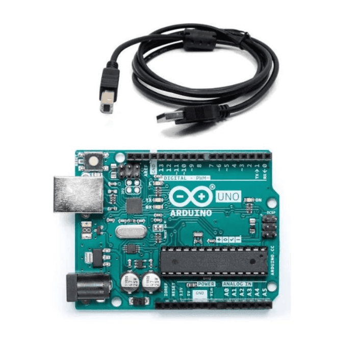
- Arduino UNO - 2.
- 433MHz RF Transceiver module - 1
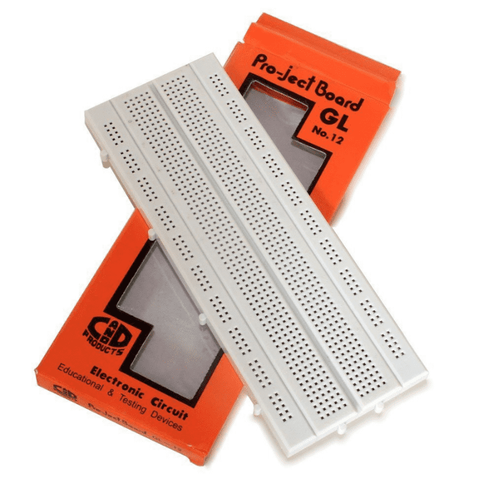
- Breadboard - 2
- LED (Any color) - 1
- Push Button - 1
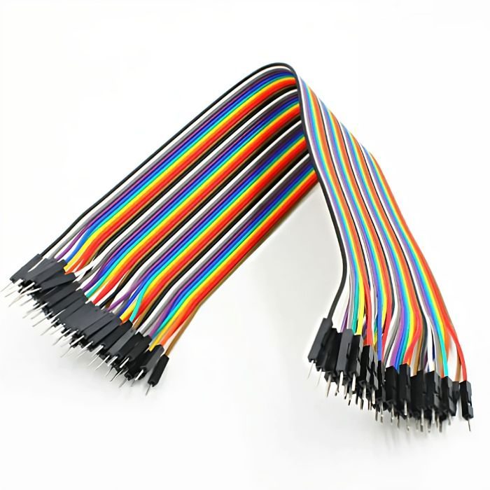
- Male to male jumper cable - As required
read more : Which Arduino Board to Buy
How does the 433 MHz RF module work?

The block diagram above depicts the entire workflow of the RF Module. We'll look at how the RF transmitter and receiver module works in detail.
Transmitter working:
This radio frequency (RF) transmitter module operates at 434MHz and employs Amplitude Shift Keying (ASK). The transmitter module receives serial input from a microcontroller and transmits it via RF. The transmitted signals are then received by the receiver module, which is located at the opposite end of the transmission path.

When the Arduino's DATA input pin is set to logic HIGH, the oscillator begins generating a constant RF output carrier wave at 434 MHz, and when the DATA is set to logic LOW, the oscillator stops producing the RF wave. Amplitude Shift Keying is the name given to this technique.
read more : Fire Detection And Notification Alarm using Arduino
Receiver Working:

The receiver module receives the data in the form of a signal and sends it to the data pin. The data received by the module is always encoded and can be decoded using either the microcontroller or the decoder.
The RF receiver module comprises an RF tuned circuit and a couple of Operational Amplifiers to amplify the received carrier wave from the transmitter. The amplified signal is then further fed to a PLL (Phase Lock Loop) later it is received by the decoder which decodes the output stream and gives better noise immunity.
What is ASK?
As previously stated, these modules use a technique known as Amplitude Shift Keying (ASK) to send data over radio frequency signals. The amplitude (i.e., the level) of the carrier wave (in our case, a 433MHz signal) is changed in response to the incoming data signal in Amplitude Shift Keying. This is similar to the analog technique of amplitude modulation, which you may be familiar with if you listen to AM radio. Because there are only two levels to consider, it is sometimes referred to as binary amplitude shift keying. Consider it a toggle switch.
- For Digital 1 – This drives the carrier at full strength.
- For Digital 0 – This cuts the carrier off completely.
read more : What is Arduino UNO
This is what the Amplitude modulation looks like:

The advantage of Amplitude Shift keying is that it is very simple to implement. The decoder circuitry is quite simple to design. Furthermore, ASK requires less bandwidth than other modulation techniques such as FSK (Frequency Shift Keying). This is one of the reasons for the low price.
Interfacing 433Mhz RF Module with Arduino
The components listed in the components required section are required for interfacing a 433MHz Rf Module with an Arduino.
The following is the Arduino UNO connection diagram for the transmitter and receiver modules
Transmitter module with Arduino UNO:

The connection for the transmitter side has to be made as per the above diagram. You can use any Arduino board for this project.
read more : HAND WASH TIMER USING ARDUINO
|
VCC pin of the Transmitter module |
5V pin of Arduino |
|
GND pin of the Transmitter module |
GND pin of Arduino |
|
DATA pin of the Transmitter module |
GPIO 12 of Arduino |
|
Pin 1 of the push-button |
GPIO 6 fo Arduino |
|
Pin 2 of the push-button |
GND pin of Arduino |
Receiver module with Arduino UNO:

The connection for the receiver side must be made as shown in the diagram above. For connecting the transmitter module, we will be using the second Arduino UNO board.
|
Both the VDD pins of the Receiver module |
5V pin of Arduino |
|
3 GND pins of the Receiver module |
GND pin of Arduino |
|
DATA pin of the Receiver module |
GPIO 11 of Arduino |
|
Positive terminal of LED via a 330-ohm resistor in series |
GPIO 6 fo Arduino |
|
Negative pin of LED |
GND pin of Arduino |
read more : Top 10 Robotic Projects for Beginners
Source code for Transmitter module:
|
#include <VirtualWire.h> |
We used a library called VirtualWire.h in the preceding code. In this code, we call functions from the VirtualWire.h library, pass the PIN to which the transmitter module's DATA pin is connected, and send data from the transmitter to the receiver via RF signal. We have used an if, else statement in the code. We specified in this if, else statement that when the pushbutton is pressed for the first time, the character’s data must be transmitted to the receiver. When the button is pressed a second time, the character 'b' must be sent to the receiver.
Source code for Receiver module:
|
|
The above code is used for receiver module. In the code, we have passed the pin number to which the DATA pin of the receiver is connected. And we have declared a pin for connecting LED. The if, else statement is used to check the condition of the received data. If the character ‘a’ data is received, then the LED will be turned ON. And when the character ‘b’ is received, then the LED will be turned OFF.
Procedure:
- Make connections as per the circuit diagram on the transmitter and the receiver side.
- Upload the respective code to both the Arduino boards. (Transmitter code on transmitter Arduino and Receiver code on receiver Arduino)
- Once the connections and the programming are done, it's time to see the output.
- Turn ON both the Arduino and place it a distance below 3 meters in indoors.
- Next, press the push-button on the transmitter side, the LED on the receiver side should turn ON. Again when you press the push button for the second time, the LED on the receiver side will be turned OFF.
- Hence, we have successfully established a communication link between the transmitter and the receiver wirelessly through RF signals and transmit data from the transmitter to the receiver.
read more : What is the microcontroller used in Arduino UNO?
Conclusion:
In this blog, we have learned about RF technology and how to use the RF technology using Arduino and RF modules. We have seen, what is RF in Arduino? What is a 433MHz RF module? The working principle of RF modules, as well as the components required, connections, source code, and how to interface it with Arduino and wirelessly communicate data between transmitter and receiver. So whether you're building a home automation system, a remote control car, or anything in between, the 433MHz RF module is definitely worth considering. With its low cost, easy availability, and excellent performance, it's no wonder why it's such a popular choice among hobbyists and professionals alike. So what are you waiting for? Start exploring the possibilities today!
If you appreciate our work don't forget to share this post and leave your opinion in the comment box.
Please do check out other blog posts about Interfacing ACS712 with Arduino , Arduino Interfacing with Ultrasonic Sensor , LED Interfacing with Arduino , Interfacing GSM Module with Arduino , Interfacing MAX30100 Pulse Oximeter with Arduino , IR Sensor Interfacing with Arduino , How to connect ZMPT101B to Arduino and How to use Buzzer with Arduino.
Make sure you check out our wide range of products and collections (we offer some exciting deals!)