


INTRODUCTION
Welcome to the exciting journey through Arduino projects! In this demo, we'll show you how to create a simple yet fun traffic light using Arduino, a fantastic project for beginners. By combining a simple circuit and a little code, you can replicate the functionality of a traffic light in a fun and engaging way. The step-by-step video tutorial below guides you through each step of this project, making it accessible even to those just starting out with Arduino. Get ready to dive into the world of programming and electronics as you bring this awesome traffic light project to life. Let’s light the way together!
COMPONENTS
To create the traffic signal using Arduino UNO you need the following components:
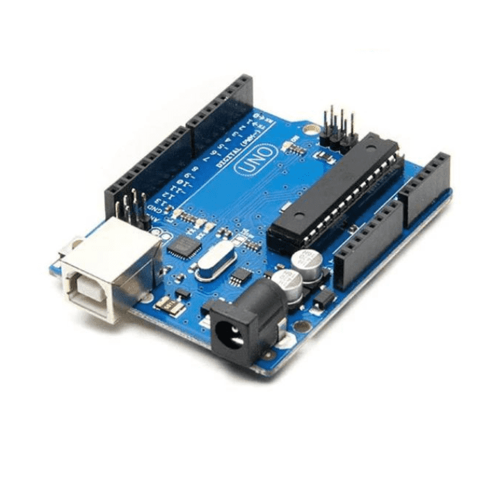
Arduino UNO

Arduino uno is an open-source microcontroller based on the processor ATmega 328P.
6 Analog pin inputs, 14 digital pins, a USB connector, a power jack and an ICSP (in-circuit Serial programming) header.
One of its notable features is the USB interface, enabling easy programming and serial communication. The board can be powered via USB or an external supply (7-12V), with an onboard voltage regulator ensuring a stable 5V supply. A reset button allows for program restarts, and built-in LEDs, including a power indicator and one on pin13, offer visual feedback.
5mm LED RED, YELLOW & GREEN

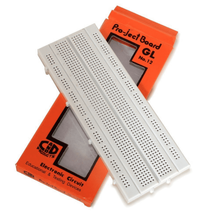
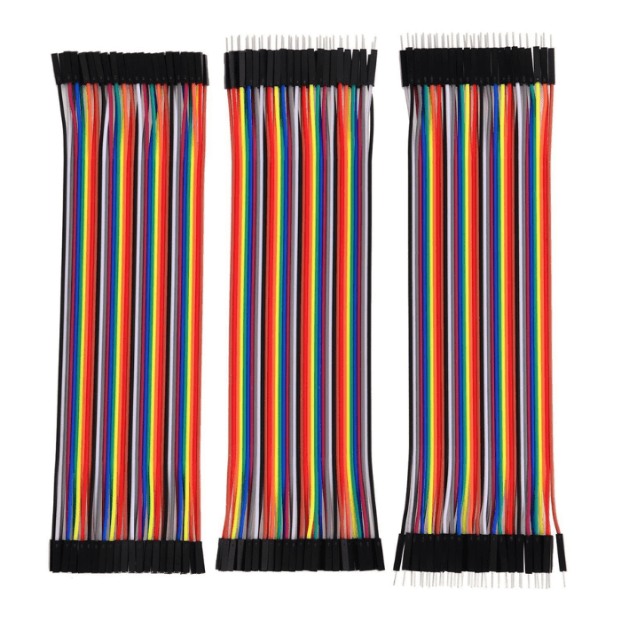
Breadboards and Jumper Wires

Used to create temporary circuits and connect things that don’t have connections.
Connections
|
LEDs |
ARDUINO UNO |
|
GND pin of all LED |
GND |
|
RED LED VCC PIN |
PIN 9 |
|
YELLOW LED VCC PIN |
PIN 8 |
|
GREEN LED VCC PIN |
PIN 7 |
Ensure that the connections are made accurately on the Arduino this table serves as a quick reference guide for setting up the circuit.

ARDUINO CODE
int red = 9;

int yellow = 8;

int green = 7;


void setup(){


  pinMode(red, OUTPUT);

  pinMode(yellow, OUTPUT);

  pinMode(green, OUTPUT);


}


void loop(){

  digitalWrite(red, HIGH);

  delay(20000);

  digitalWrite(red, LOW);


  // Yellow stays on for 2 seconds

  digitalWrite(yellow, HIGH);

  delay(2000);

  digitalWrite(yellow, LOW);


  digitalWrite(green, HIGH);

  delay(20000);

  digitalWrite(green, LOW);

}
CODE EXPLAINATION
- Variable Declarations: int red = 9;int yellow = 8;int green = 7; These lines declare three integer variables red yellow and green and assign them the pin numbers where the respective LEDs are connected.
- Setup Function: pinMode(red, OUTPUT); pinMode(yellow, OUTPUT);pinMode(green, OUTPUT); These lines configure the pins connected to the LEDs as output pins, allowing us to control the LEDs.
- Loop Function: digitalWrite(red, HIGH), delay(20000); digitalWrite(red, LOW); This sequence turns on the red LED, waits for 15 seconds, and then turns it off. digitalWrite(yellow, HIGH); delay(2000); digitalWrite(yellow, LOW); This sequence turns on the yellow LED, waits for 2 seconds (as per the modification), and then turns it off. digitalWrite(green, HIGH);delay(20000); digitalWrite(green, LOW); This sequence turns on the green LED, waits for 20 seconds, and then turns it off.
- Looping: - Since this code is within the loop()function, it repeats these actions indefinitely, cycling through turning on each LED for a specific duration and then turning it off.
OVERALL FUNCITONALITY
The overall functionality of the project is to simulate a basic traffic light system using Arduino and three LEDs of different colours: red, yellow, and green. The program follows a predefined traffic light sequence commonly found at intersections. The main functionalities can be summarized as follows:
- Traffic Light Control: The program controls the illumination of the red, yellow, and green LEDs to replicate the standard traffic light phases: red for stopping, yellow for caution, and green for go.
- Sequential Operation: The traffic light operates in a sequential manner, transitioning through the standard traffic light cycle: red, yellow, green, and back to yellow.
- Timing Control: Precise timing is implemented using the delay function to simulate the duration of each phase (e.g., 15 seconds for red, 20 seconds for green, 1 second for yellow).
- Repetition: The entire sequence of red, yellow, green, and yellow is repeated in a continuous loop, creating a realistic simulation of a traffic light's cyclical behavior.
- Configurability: The code allows for easy adjustments to the durations of each phase, making it adaptable to different traffic scenarios or user preferences.
CONCLUSION
In conclusion, the Arduino-based traffic light simulation project successfully emulates the fundamental functionality of a traffic light system. By controlling three LEDs – red, yellow, and green – in a sequential manner, the program replicates the typical traffic signal phases. The code incorporates precise timing through delays, allowing the simulation to mirror the durations associated with each phase.
The project's simplicity and configurability make it an excellent starting point for educational purposes or prototyping in the field of traffic control systems. The sequential operation and repetition in a loop provide a realistic simulation of a traffic light's cyclical behaviour. Moreover, the ability to easily adjust the timing parameters allows for customization, enabling developers to tailor the simulation to specific scenarios or preferences.
While this project serves as a foundational framework, it can be expanded upon for more sophisticated applications. Integration with sensors, additional LEDs, or communication modules could enhance the project's capabilities, making it suitable for broader smart city initiatives or traffic management systems. Overall, the project demonstrates the versatility of Arduino in creating tangible simulations for educational and practical purposes, laying the groundwork for further exploration and innovation in the realm of traffic control and smart city technologies.