


Recently bought a Raspberry Pi and want to start embedded programming? In this blog, we will look at the most basic and getting started example for embedded programming using Raspberry Pi: Turning on an LED using Raspberry PI’s GPIO pins. Before we get started, below is a small background on Raspberry Pi and LEDs in case you are new to the world of DIY electronics.
Background
Raspberry Pi
Raspberry Pi is a series of small Single Board Computer or SBC. It primarily runs a custom version of Linux called Raspberry Pi OS but can also run other flavours of Linux build specifically for the Raspberry Pi hardware. It contains 4 USB ports, ethernet port, 2x micro HDMI ports and USB C for power. It also contains a 40-pin GPIO header which can be used to interface various sensors and actuators.
To interface the LED, we will be using one of these GPIO headers and we will be controlling the LED by giving the signal to the GPIO header it is connected to.
Along with simple digital inputs and outputs, the GPIO headers can also be used to interface I2C, SPI, UART sensors as well and all pins are capable of PWM as well. This is great for experiments where we would like to vary the output voltage to the sensor/device it is connected to.
LEDs
LEDs or light emitting diode are semiconductor devices that emits light when a forward current passes through it.
LEDs are popularly used these days and are rapidly replacing previous technologies such as incandescent bulbs and CFLs since LEDs are much more efficient, can be made to produce almost any colours and are much more versatile depending on the requirement.
It comes in various shapes and forms depending on the application. For example, i
- It comes in tube lights and bulb shapes for homes
- It can be made intro strips for all kinds of accent lighting
- It can be made into a tiny pixel like grid for TVs, displays, smartphones, etc
- It can also be turned into various shapes for decors and sign boards
LEDs come in single colour form or it can also come in RGB layout (red, green & blue) where three separate LEDs are combined into 1 unit to produce any colour by varying intensities of each LED.
For example, red light can be emitted by only turning on the red LED, while yellow can be emitted by turning on the Red and Green LED, causing the lights to mix and appear as yellow. If all three LEDs are on ie. red, green and blue, we get white light.

Single colour LEDs typically come with two leads, anode and cathode, which takes in positive voltage and negative voltage respectively.
RGB LEDs typically come in 4 lead variants, where each colour corresponds to a pin, along with a common connector. It can either come common anode or common cathode, where common anode config uses 3 cathodes for 3 colours and a common positive pin, while common cathode uses 3 anodes for 3 colours and a common cathode pin for ground

Components Required
Following is the list of components that you will require:
If you don't have the necessary components, you can click on the name of the components and get all the required components from our store.
1. Raspberry Pi 4

You will need a Raspberry PI board installed with the Operating system. Here we have used the latest version of the Raspberry Pi board which is model 4 B. If you haven't installed the operating system then you can go to the official Raspberry PI website and install the Raspbian operating system and then follow this blog.
2. LED

You will need a Light-emitting Diode (LED).
3. Resistor - 330 ohms (color code: Orange Orange Brown)

Any value between 330 ohms to 1k works. LEDs can tolerate a specific amount of current if you pass current beyond this value they will be damaged. To protect this, we are using a 330-ohm resistor for limiting or reducing the current through the LED.
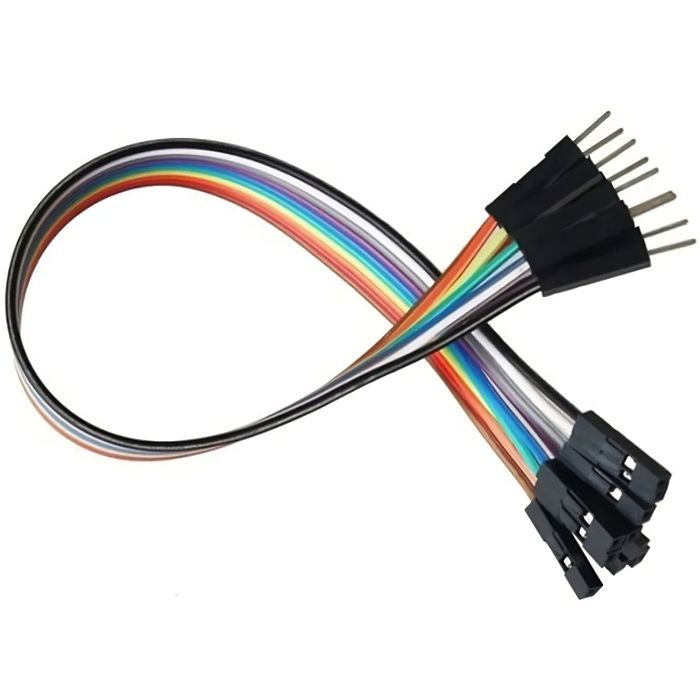
4. Male-to-Female Jumper Wires ( Quantity -2)
These are required for doing the connections between Raspberry PI and LED.

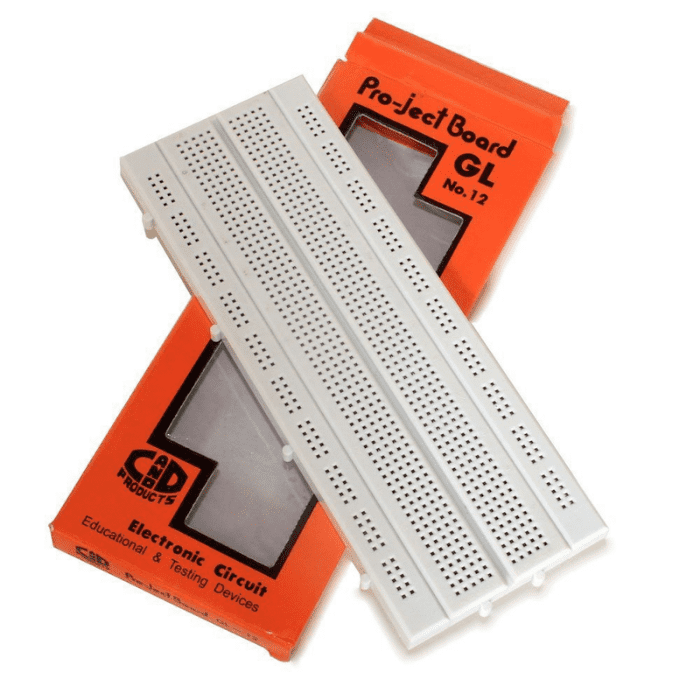
5. Breadboard

Required for doing the wiring.
Once we have all the components ready before making the connections let's first understand the Raspberry Pi General Purpose Input Output (GPIO) pinout.
Read our blog explaining the interfacing ultrasonic sensor raspberry pi, Which provides a concise guide on interfacing an Ultrasonic Sensor (HC-SR04) with Raspberry Pi 4 GPIO.
Raspberry PI’s GPIO Pins
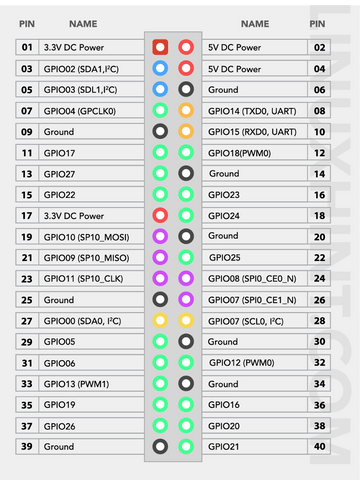
Raspberry PI GPIO pins are used for interfacing the Raspberry Pi with the outside world. This interfacing is done by connecting sensors, actuators, LEDs, etc to the GPIO pins. All GPIO pins on Raspberry Pi are digital i.e. they can output just a digital high signal (3.3V) or a digital low signal (0V). Now we know what GPIO Pins are and what they are used for. Now let's build the circuit!
Building Circuit
Place LED and resistor as shown in the below image.

Take a male to female jumper and connect one end to the ground of the RPi board and the other to the shorter terminal of LED (cathode) and GPIO pin 23 to the resistor.
Finally, the connections are done now let's write and understand the blinking code.
Code
import RPi.GPIO as GPIO
import time

LED_PIN = 23

GPIO.setmode(GPIO.BCM)
GPIO.setup(LED_PIN, GPIO.OUT)

try:
    while True:
        GPIO.output(LED_PIN, GPIO.HIGH)
        time.sleep(1)
        GPIO.output(LED_PIN, GPIO.LOW)
        time.sleep(1)
except KeyboardInterrupt:
    GPIO.cleanup()
Open the python IDE and write the above code and run it. This code blinks led every second. To stop the program press CTRL+C. This will stop the execution. Now let's understand the code line by line.
Code Explanation
import RPi.GPIO as GPIO
This module provides functionalities to control the GPIO pins
If you want to see what all functions this module provides you can type the following code in the terminal. This will list all the functions this module contains. You can do this for any python module.
|
python3 >>> import(RPi.GPIO) |
|
import time |
Time module is used to add delays in the program.
|
LED_PIN = 23 |
Here we create a variable LED_PIN and store 23 in it.
|
GPIO.setmode(GPIO.BCM) |
This line activates the Broadcom chip-specific number by accessing the “set mode” function from the GPIO module.
|
GPIO.setup(LED_PIN, GPIO.OUT) |
This sets LED_PIN 23 as output.
Then we used pythons try and except blocks. This block is used for handling exceptions. In the try block, we write the normal code that is to be executed, and in except block we write the exceptions which we want to handle.
|
try: |
In try block we have used a while loop and we have the condition to be always true so the statements inside this loop will execute forever.
|
GPIO.output(LED_PIN, GPIO.HIGH) |
Inside the while loop, the above line makes the LED pin HIGH
|
time.sleep(1) |
This line calls the sleep function from time module and we have passed 1 as in the argument so it gives a delay of 1 second. By default time.sleep() function takes arguments in seconds.
|
GPIO.output(LED_PIN, GPIO.LOW) |
The above lines set the led pin as LOW and give a delay of 1 second.
|
except KeyboardInterrupt: |
KeyboardInterrupt is an exception that occurs when you press CTRL+C when the program is running. So, whenever this exception occurs this block gets executed.
GPIO.cleanup() cleans/resets all the pins used in this program. It resets them as input.
If you forget to clean the pins and let's say in a scenario you have kept one of the pins as high and you connect this pin to the ground which can lead to a short circuit. To prevent this we use this GPIO cleanup function.
Conclusion
In this blog post, we have learned that how to turn on an LED with your Raspberry Pi's GPIO pins and it is a great way to dive into the world of physical computing. With just a few simple steps, you can control the behaviour of an LED and unleash your creativity to build all sorts of projects. Not only is it fun and rewarding, but it's also a great skill to have for those interested in pursuing a career in tech. So, get your Raspberry Pi and start experimenting with its GPIO pins to see what kind of amazing things you can create!
If you appreciate our work don't forget to share this post and leave your opinion in the comment box.
Please do check out other blog posts about Ultrasonic sensor with raspberry pi 4 , Interfacing MPU6050 accelerometer with Raspberry Pi , Difference Between Arduino and Raspberry Pi , Raspberry Pi vs Beaglebone ,DS18B20 with Raspberry Pi Pico , DS18B20 with Raspberry Pi Pico using MicroPython , How to use Raspberry Pi as node in LoRAWAN , NODE TO NODE COMMUNICATION ON LORA WITH RASPBERRY PI 4 and Controlling Speed and Led Brightness of Robot Using Raspberry Pi.
Make sure you check out our wide range of products and collections (we offer some exciting deals!)