


What is a Servo Motor?
A Servo Motor is a type of motor that is used to control the angular position of a shaft. It is a closed-loop control system that consists of a motor, a gear train, and a feedback sensor. The motor rotates the shaft to a specific position, and the feedback sensor ensures that the shaft stays at that position.

The motor receives a control signal from a microcontroller or other controller, which tells it the desired angular position of the shaft. The servo motor then rotates the shaft to the desired position and holds it there. The feedback sensor, typically a potentiometer, provides feedback on the actual angular position of the shaft to the controller. The controller then makes adjustments as necessary to keep the shaft at the desired position.
Servo motors find widespread usage in robotics, automation systems, and various applications that demand accurate control over the angular position of a shaft. These motors are usually compact in size, possess a favorable torque-to-weight ratio, are reasonably affordable, and offer ease of control.
Servo Motor Working Mechanism
The servo motor working mechanism is based on the control system called the "closed-loop control system". The closed-loop control system has a feedback mechanism that compares the actual position of the servo motor with the desired position.
The servo motor receives a control signal from a microcontroller or other controller, which tells it the desired angular position of the shaft. The motor then rotates the shaft to the desired position and holds it there. The feedback sensor, typically a potentiometer, provides feedback on the actual angular position of the shaft to the controller.
The controller compares the actual position of the servo motor with the desired position and generates an error signal. This error signal is used to adjust the motor's position so that it can reach the desired position.
When it comes to a PWM signal, the position of the servo motor is controlled by the duty cycle of the PWM signal. The servo motor's position is directly proportional to the duty cycle. Alternatively, in the case of an analog voltage, the voltage level is employed to control the position of the servo motor.
To summarize, the working mechanism of a servo motor relies on a closed-loop control system that utilizes a feedback sensor. This system continuously compares the actual position of the servo motor with the desired position and makes necessary adjustments to ensure the shaft remains at the desired position.
Servo Motor Working Principle
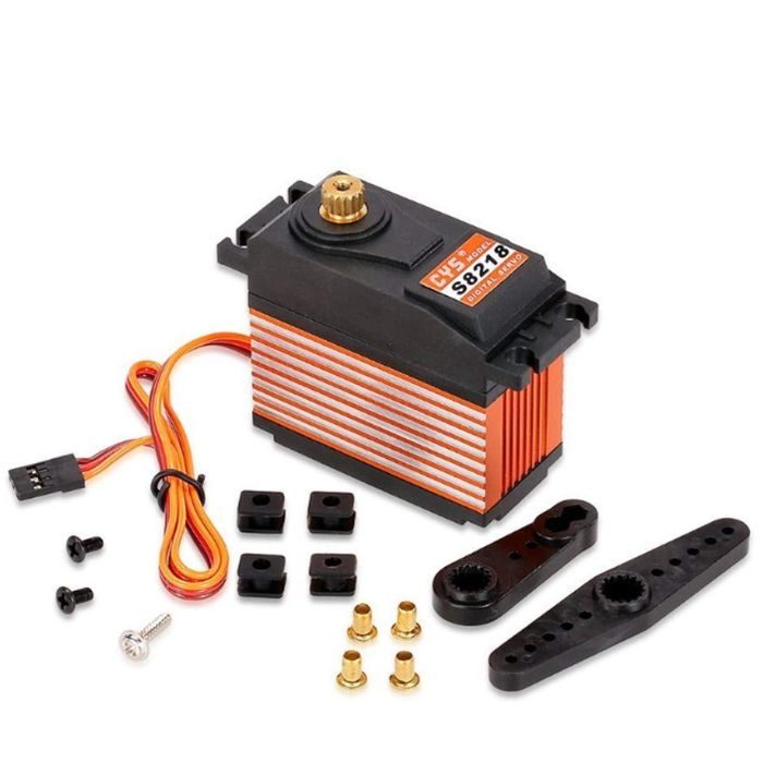
A motor (either DC or AC), a potentiometer, a gear assembly, and a controlling circuit make up a servo. First, we employ a gear arrangement to lower the motor's RPM and boost its torque. Imagine that the potentiometer knob is set so that, while the servo motor shaft is in its original position, no electrical signal is produced at the potentiometer's output port. The error detection amplifier's second input terminal is now supplied with an electrical signal. Now, a feedback mechanism will process the difference between these two signals—one coming from the potentiometer and the other coming from external sources—and deliver output in the form of an error signal. This erroneous signal serves as the motor's input, and the motor begins to rotate. Now that the potentiometer and motor shaft are attached, a signal will be produced by the potentiometer as the motor rotates.
Consequently, the output feedback signal of the potentiometer changes as its angular position does. After some time, the potentiometer's position reaches a point where its output matches the supplied external signal. Because there is no distinction between the externally supplied signal and the signal generated at the potentiometer in this state, there will be no output signal from the amplifier to the motor input, and the motor will stop turning.
Interfacing Servo Motors with Microcontrollers
Servo motors can be easily interfaced with microcontrollers using a simple control signal. The control signal is typically a PWM signal, which is generated by the microcontroller. The PWM signal controls the position of the servo motor by adjusting the duty cycle of the signal. The servo motor's position is proportional to the duty cycle of the PWM signal. Then the Vcc, Gnd is given to 5v, Ground of microcontroller. There is an example below which depicts the interfacing of the Servo motor with Arduino.

Controlling Servo Motor
Controlling the servo motor is done using the signal terminal and controlling it by varying the PWM. The control wires offer PWM (Pulse with Modulation), which is used to drive the servo motor. There are three different pulse ranges: minimum, maximum, and repetition rate. A servo motor's neutral state allows it to turn 90 degrees in any direction. Every 20 milliseconds (ms), the servo motor expects to receive a pulse; the pulse's duration determines how far the motor will turn. For example, when a 1.5ms pulse is sent to the servo motor, it will rotate to the 90° position. If the pulse duration is shorter than 1.5ms, the shaft will move to the 0° position. Conversely, if the pulse duration is longer than 1.5ms, the servo motor will turn to the 180° position.

The duration of the pulse applied to the servo motor's Control PIN determines the angle at which it rotates, according to the PWM (Pulse Width Modulation) concept. The basic components of a servo motor are a DC motor, a variable resistor (potentiometer), and some gears. Gears transform a DC motor's high-speed force into torque. To determine the angle and stop the DC motor at the necessary angle, the potentiometer is linked to the servo's output shaft.
Conclusion
A servo motor is a rotary actuator that utilizes feedback to regulate the angular position of a shaft. It comprises a motor, a gear train, and a feedback sensor. The fundamental principle behind the operation of a servo motor is a closed-loop control system. This system constantly compares the current position of the servo motor with the intended position, and accordingly makes any necessary adjustments to maintain the shaft at the desired position. Servo motors can be easily interfaced with microcontrollers and controlled using a PWM signal or analog voltage.
If you appreciate our work don't forget to share this post and leave your opinion in the comment box.
Please do check out other blog posts about Popular electronics
Make sure you check out our wide range of products and collections (we offer some exciting deals!)